Fading
The sudden decrease of the friction factor owing to an overheating of the friction pairing. Due to the servo effect, fading will mostly occur with band and drum brakes, whereas disc brakes are less prone to fading. Local fading may also occur after having mounted new friction linings, when the friction pairing has not yet bedded in.
Ball bearing effect
The particles rubbed off by the friction process (fine to coarse dust) are not discharged but remain between the friction surfaces. This dust gradually becomes ball-shaped. Only parts of the friction surfaces remain in contact so that the friction factor drops sharply until - in extreme cases - friction no longer exists. It is recommended that the occurrence of chamfers or tapers on feed ends is avoided because the rubbed-off particles may easily penetrate here in particular. Dust grooves of the most varied shapes will help to avoid this.
Friction linings, moulded
Essentially, they are composed of three groups of material:
1. Fibrous materials (reinforcing fibres) provide mechanical strength:
Inorganic and organic natural and synthetic fibre made of cotton, hemp, aramid, acrylic, glass, carbon, viscose etc.
2. Friction coefficient modifiers for the level of friction coefficient, temperature dissipation and wear reduction:
Mica, barium sulphate, iron, copper, brass, tin, bronze etc. in the form of powder or chips, wires, wool.
Slip additives such as graphite, lubricants etc.
3. Binding agents for the cohesion of the material mass:
Synthetic resins such as resol, novolaks and various types of caoutchouc.
Under great pressure and at a high temperature this material mass is moulded to produce the friction lining.
Friction linings, testing
The friction materials used by us are tested on a 100 FAST small-sample test stand.
The preferred technical data are:
1. Brake disc
Material No. EN-JL 1040 GG25
Brinell hardness HB30 180 - 250
Tensile strength Rm 250 - 350 N/mm²
2. Testing parameters
Contact pressure p 1 N/mm²
Velocity v 7 m/s
3. To determine the max. temperature at which the friction factor declines sharply: >> Fading
Contact pressure p 1 N/mm²
Velocity v 10 m/s
Test time up to t 90 min
The measured friction lining values result from the precisely defined parameters of the test stand. They serve exclusively for the comparison of the different friction materials. Therefore, the values found in the tables of our data sheets do not render the required local practical testing unnecessary and they must not be adopted for practical operation without restrictions.
The brake disc to be employed should be made of cast iron or steel with HB30 >= 180 or higher.
The surface of the brake disc should be finely finished (surface roughness Rz 4 -10µ).
Friction layer (sintering)
During the bedding-in of the friction pairing a friction layer of just a few μm thickness develops on the friction lining. A structural change takes place. Tiny metal particles come off the metal counter-material to enter the friction lining where they form the friction layer. This layer protects the underlying friction lining against thermal stress and is responsible for the friction properties. Subject to the individual friction pairing, this layer will form after about 200 to 300 brake actions, provided that there is no excessive thermal load.
The formation of the friction layer is not to be mistaken for >> glazing.
Friction
Friction is generated by a relative motion between friction lining and counter-material. When viewed through the microscope both surfaces reveal valleys and mountains such that they get caught on each other. Mechanical energy is required to produce the relative motion of the two surfaces in contact. By tearing off the mountains, that motion generates frictional heat and abrasive wear. Once the friction pair has bedded in, the contact pattern covers an ever larger area of the surface and moves across the friction surface.
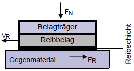
Friction factor μ (My)
The ratio of friction force to normal force, μ = FF / NF.
The friction factor is determined by the following influencing variables:
friction material / counter-material surface
roughness of the contact surfaces lubricant, dirt
velocity (slip) temperatures
These variables are partly interdependent. The effects on the friction pairing can therefore only be determined by means of tests in the local system. The values in our tables are derived from small sample tests on test stands. Accordingly, the calculation of the actual application case must take account of safety values according to the respective application.
See also >> Friction linings, testing
Stick/slip
The undesired jerking motion of friction lining and counter-material sliding over each other. The friction pair exercises a quick sequence of movements alternating between sticking, bracing, separating and sliding. This may lead to considerable vibrations perceived via a sound board as a noise (squeaking) or a judder (chatter marks). The sound board is mostly found to be an excessively light structure, e.g. friction lining carrier or counter disc made of sheet steel instead of cast iron. The stick/slip effect might cause severe damage to the entire mechanical system. Here, using our graphite-containing materials LR359 and LR353 has often prevented that effect.
Glazing
A very hard and smooth layer on the surface of the friction lining that is produced by volatile emerging substances due to excess heat. The friction factor will thus be greatly reduced. This effect may be caused by low surface pressure and high sliding speed (the friction lining slides and the work of friction is too low) or after initial full brake applications.
The hard layer may possibly be removed using emery paper (100 - 120).